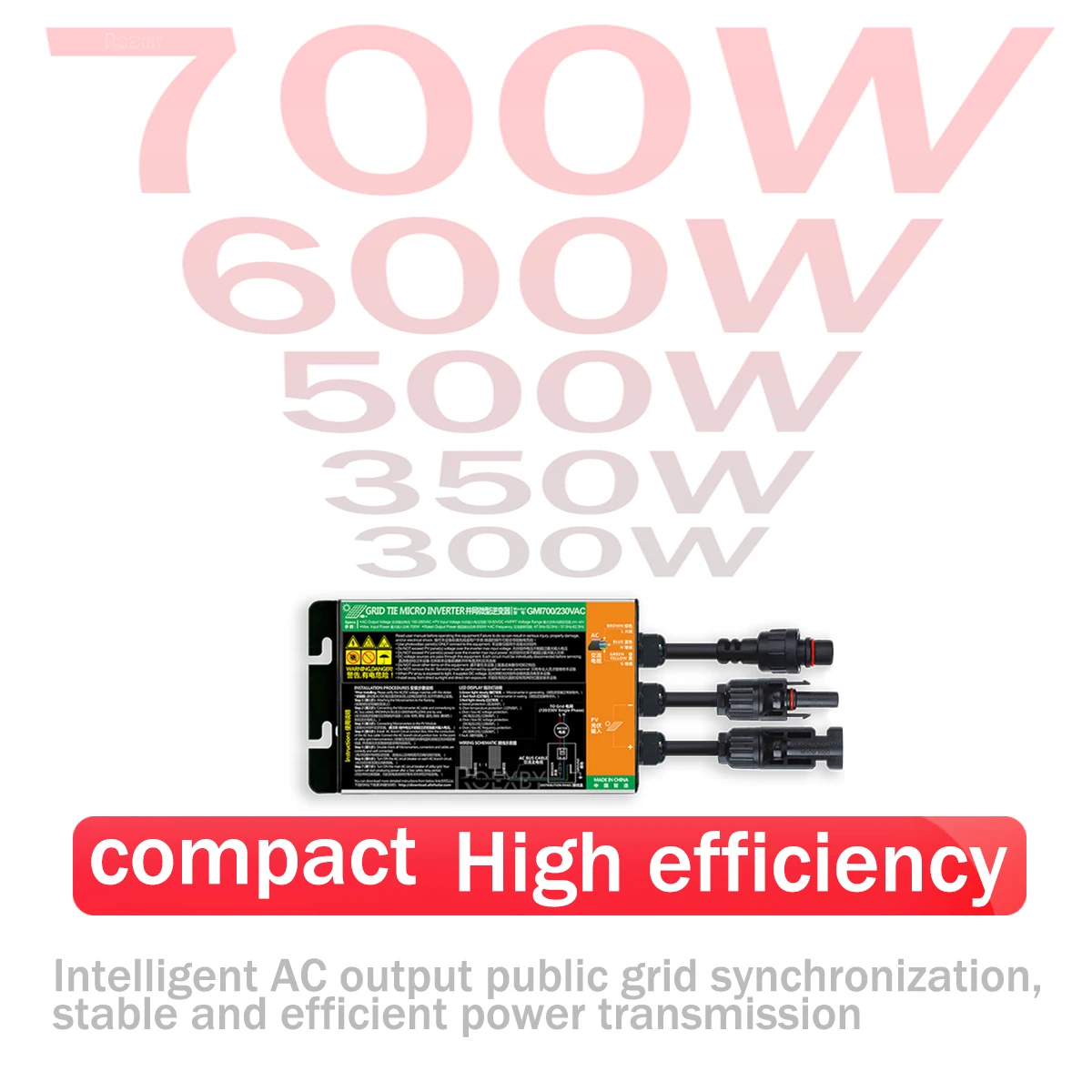
300W 350W 500W 600W 700W Micro Inverter Balcony Solar PV Grid Tie
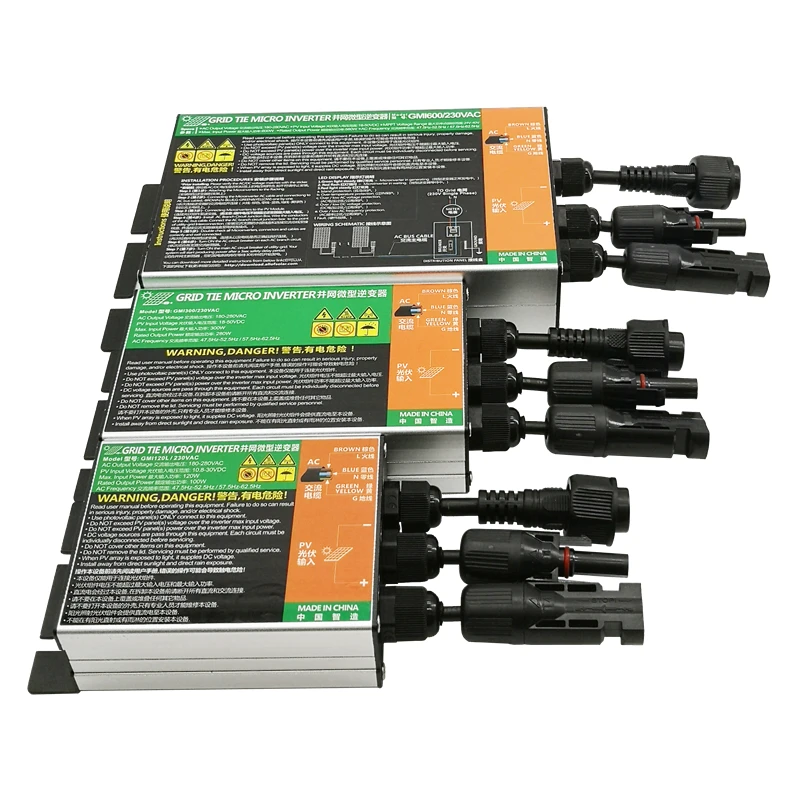
300W 350W 500W 600W 700W Micro Inverter Solar PV Grid Tie System for Home Use MPPT DC26V-46V Solar Input AC110V-240V Output
Product Description:
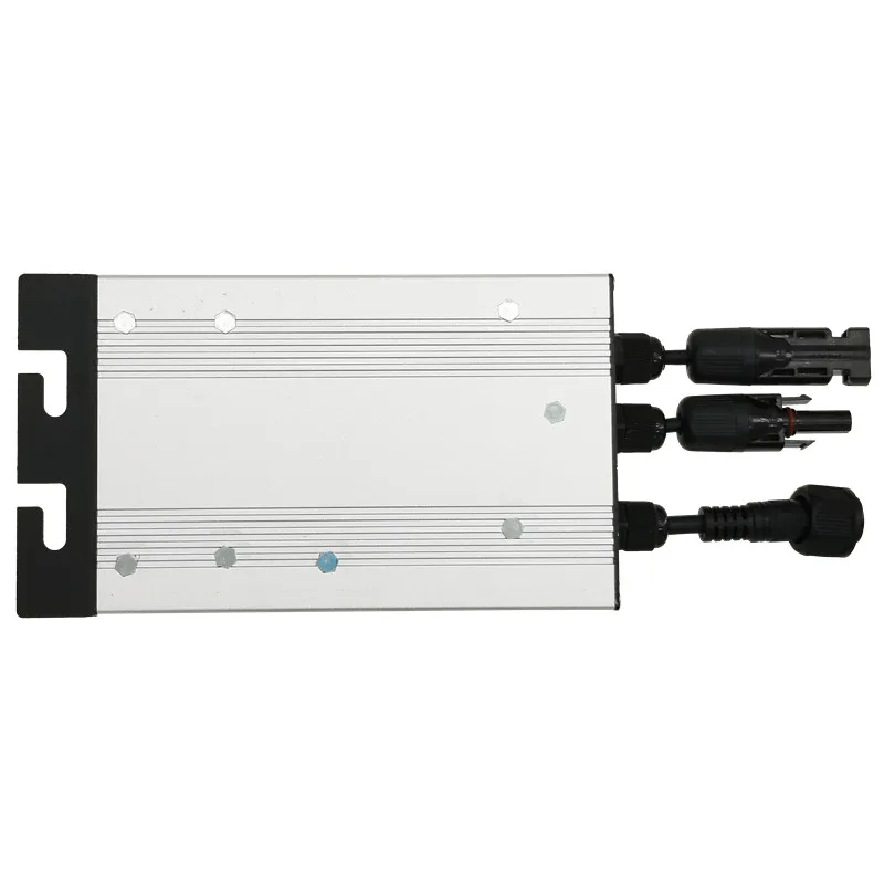
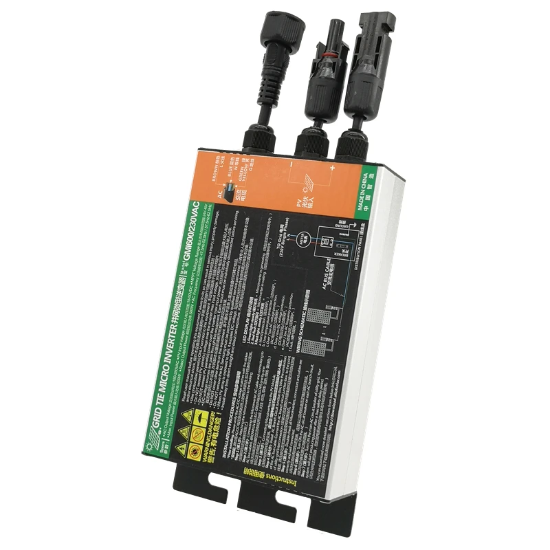
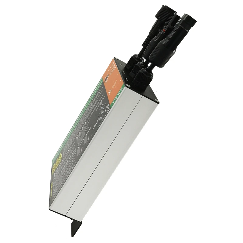
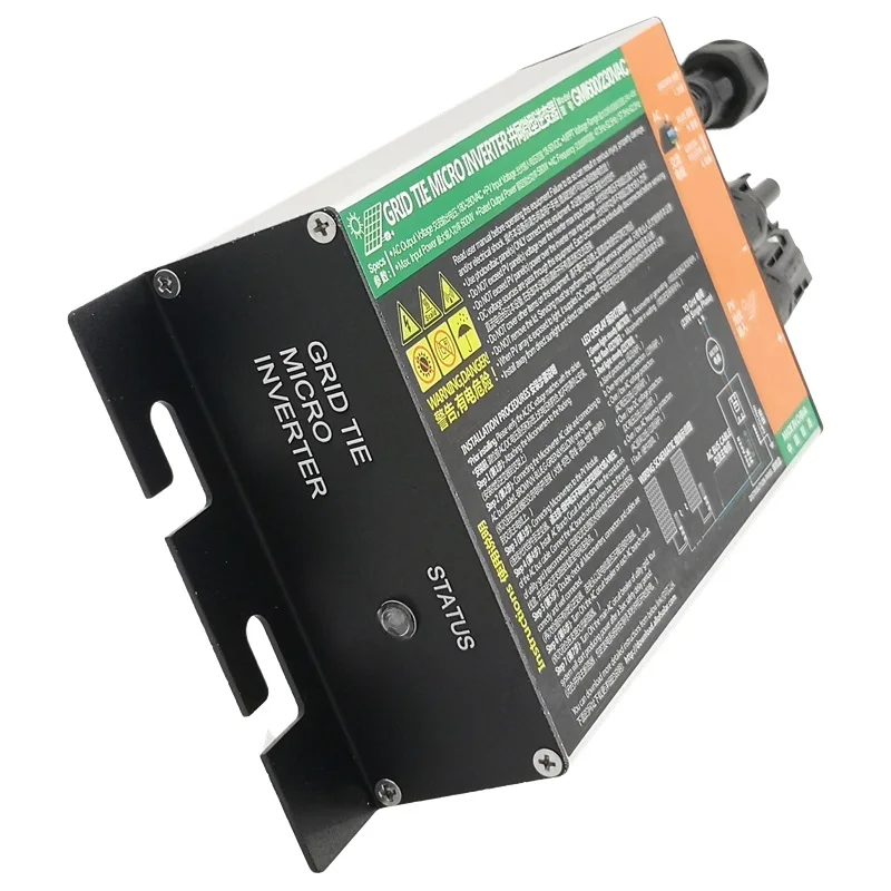
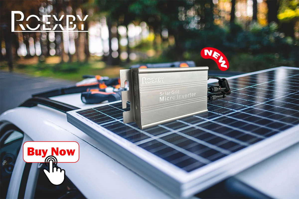
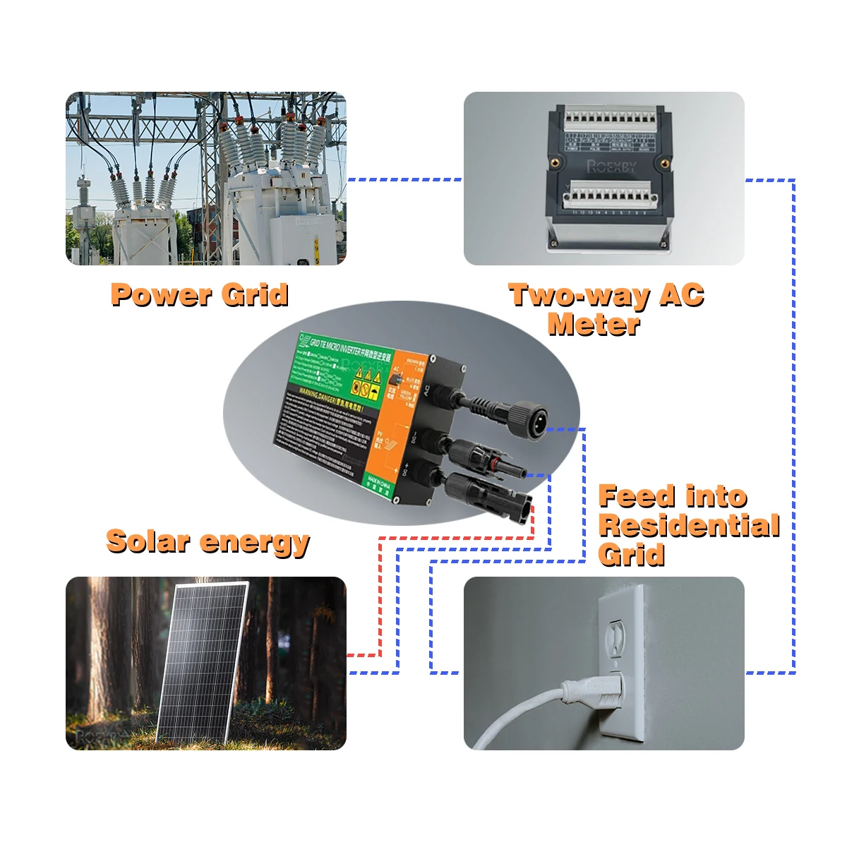
The GMI. Series 300W 350W 500W 600W 700W Solar Grid Tie Micro Inverter is a high-quality and compact device that effectively converts DC power into AC power for home and office appliances. The AC output of the smart micro inverter is synchronized and in-phase with the utility grid, ensuring the smooth and efficient transfer of electricity.
This micro inverter is designed to operate with solar panels only and has an input voltage range of 18V-50V. It can handle a maximum solar panel power of 300W/350W/500W/600W/700W and features MPPT range of 24V - 40V. It is a great choice for those who want to reduce their carbon footprint and save on electricity bills.
Specifications:
Maximum Output Power: 300W/350W/500W/600W/700W
Rated Output Power: 280W/320W/480W/580W/680W
DC Input: 18V-50V
AC Output Voltage: 120V/240V
Frequency Range: 50/60HZ Auto
MPPT range: 24V - 40V
Solar Panel Voltage: Vmp30-39V; Voc38-46V
Solar Panel Power: maximum 300W/350W/500W/600W/700W
Certification: CE
User notice:
This equipment is an ON-GRID Microinverter and must be correctly connected to the power grid to work properly. When the power grid stops working, it will also stop generating.
Do not exceed PV panel(s) voltage over the inverter max input voltage (Voc<50V).
Do not exceed PV panel(s) power over the inverter max input power.
The positive and negative poles of the solar panel cannot be reversed. Be careful when extending the solar panel cable.
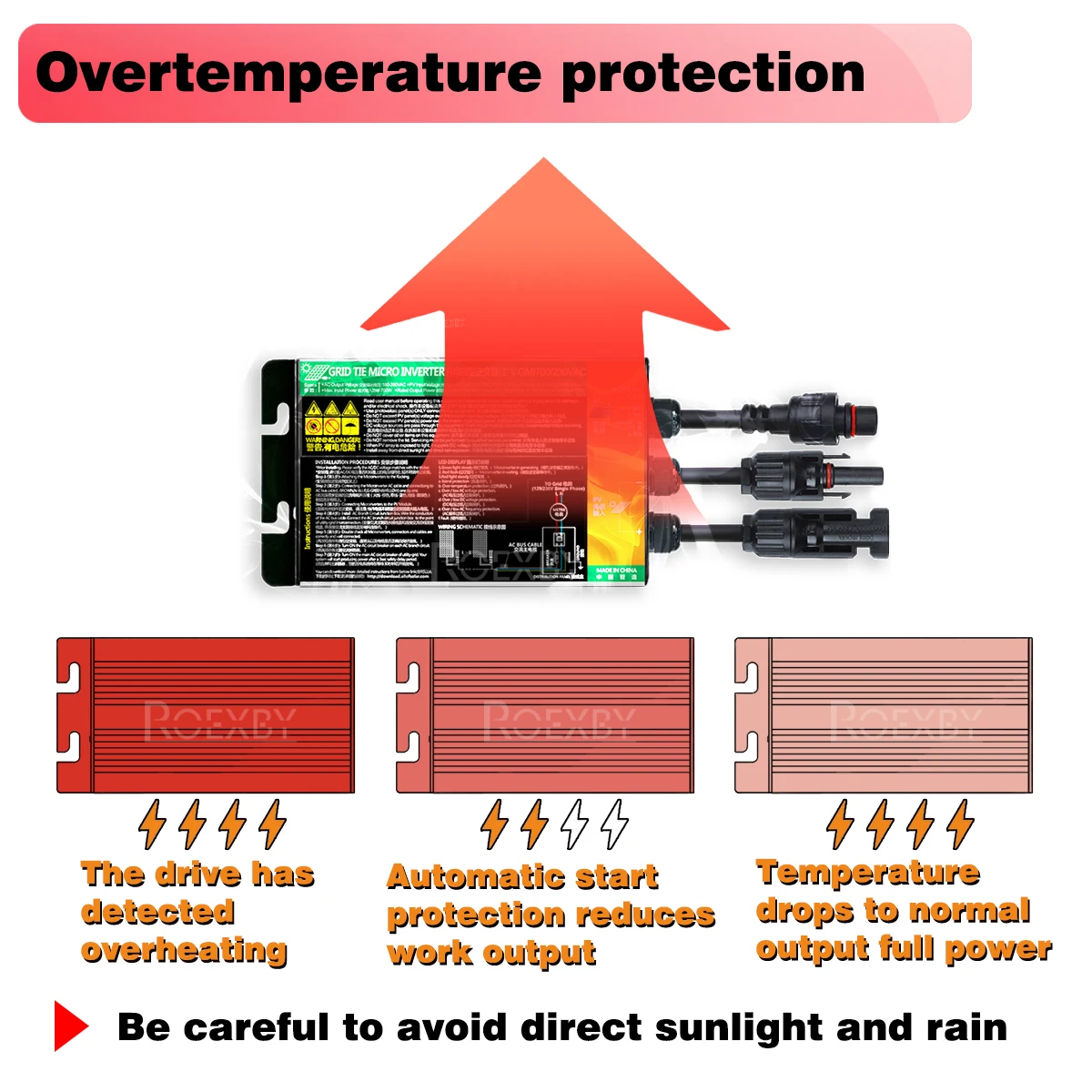
Install the inverter away from direct sunlight and direct rain exposure in a ventilated, dry, and cool place.
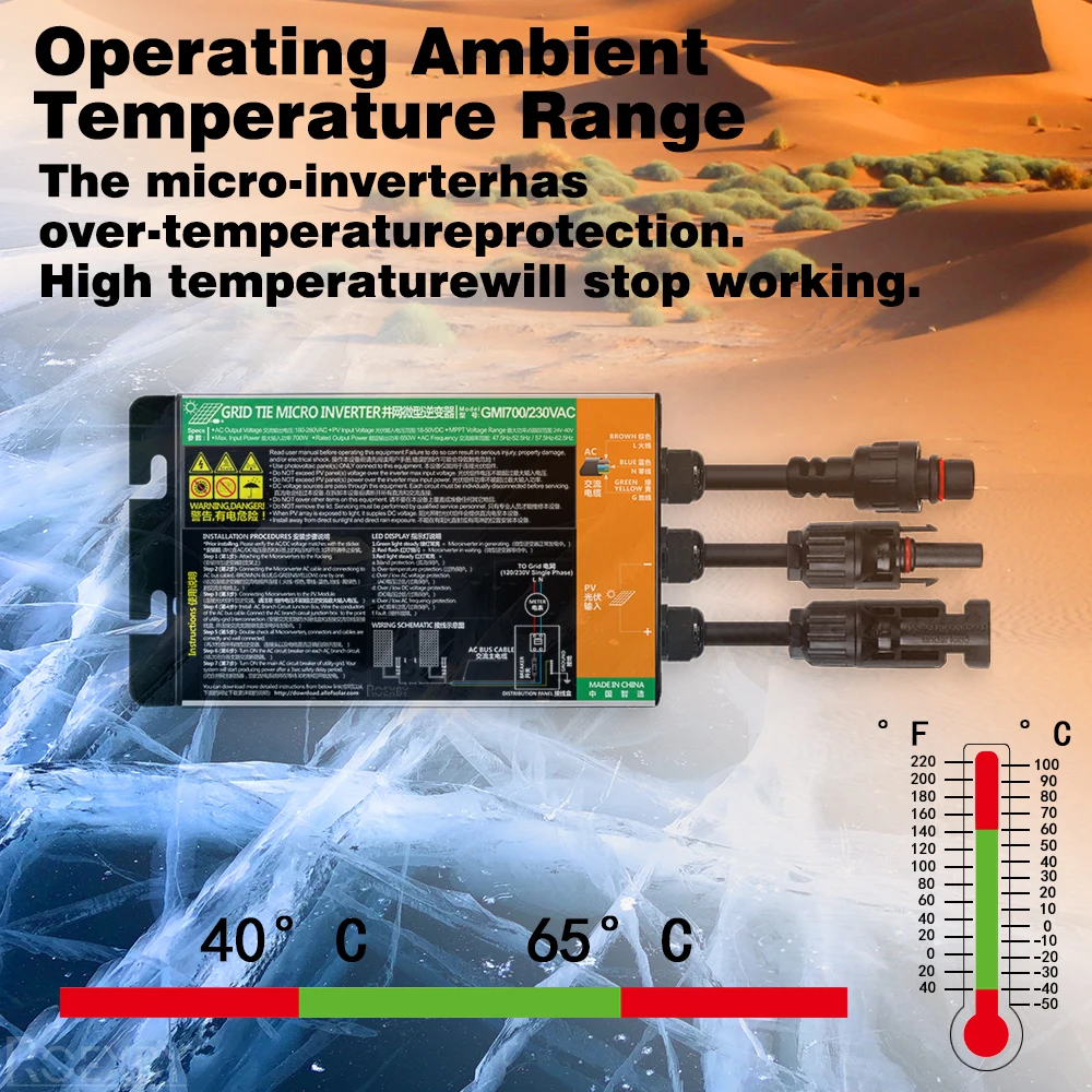
The inverter may generate heat during operation, which is normal. The inverter has over-temperature protection, and if the temperature is high, it will automatically reduce the working output efficiency or stop working. After cooling down, it will restart.
We have upgraded the drive of the inverter to better protect it. If the inverter reaches a certain temperature, it will lose half of its power. When the thermal temperature drops to normal, it will output full power again. If it still cannot output full power, disconnect and reconnect.
Micro-inverter repair:
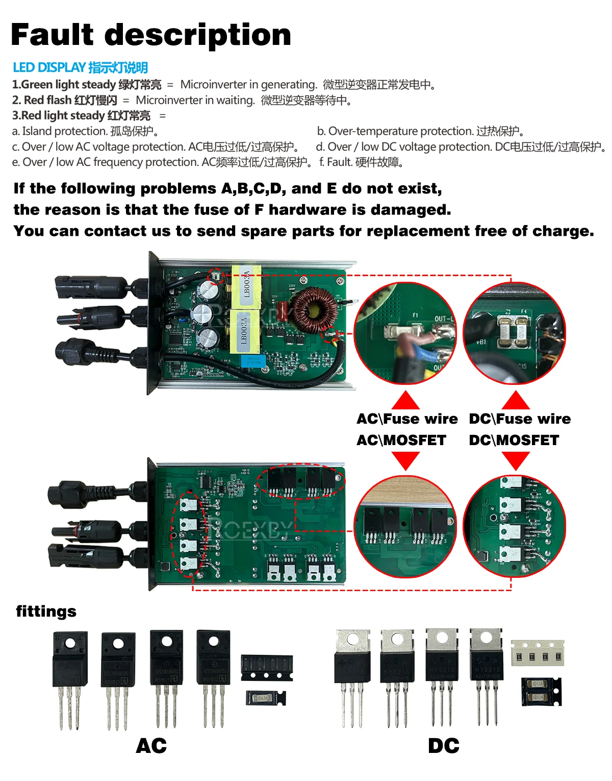
A common issue reported by our customers is that the inverter may stop working due to damaged DC or AC fuses. To help you resolve this, we offer free replacement accessories and instructional videos to guide you through the process.
If you have any questions or concerns after receiving your product, please contact us promptly. We are committed to providing high-quality after-sales service .
Voltage Tips:
Our 18-50V grid tie micro inverter requires a starting voltage of 24V and operates in the range of 18V-39V (Vmp). Please note that the Voc of your solar panel should not exceed 50V.
Using a 12V solar panel with a Vmp of 18-20V and Voc of 20-24V is not recommended, as weak sunlight may cause the working voltage to drop below 18V, leading to unstable inverter operation and damage. Instead, we suggest using solar panels with a Vmp of 30-39V and Voc of 38-46V for optimal performance.
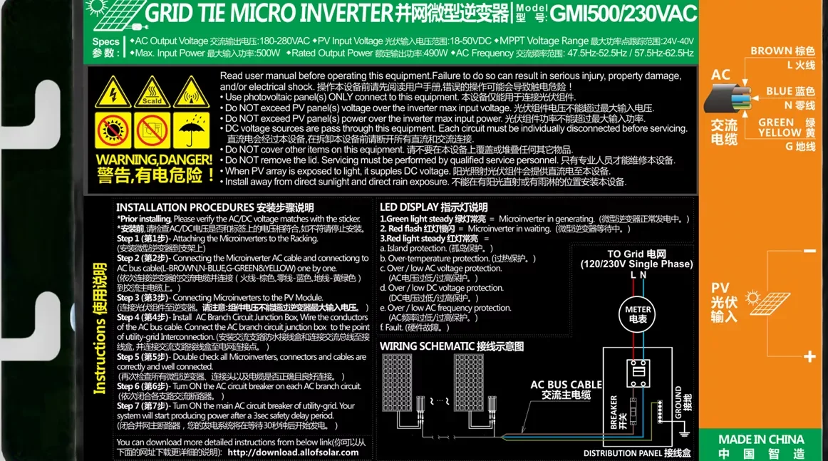
LED DISPLAY:
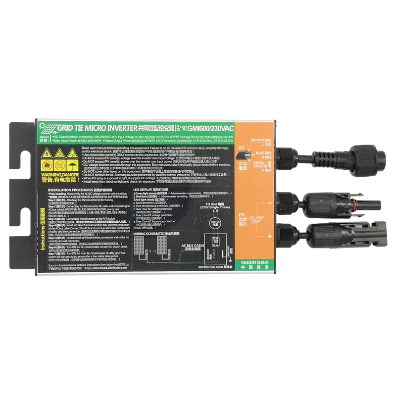
Steady green light indicates the microinverter is generating power.
Flashing red light indicates the microinverter is in standby mode.
Steady red light indicates the following protections are in place:
a. Island protection
b. Over-temperature protection
c. Over/low AC voltage protection
d. Over/low DC voltage protection
e. Over/low AC frequency protection
f. Fault protection
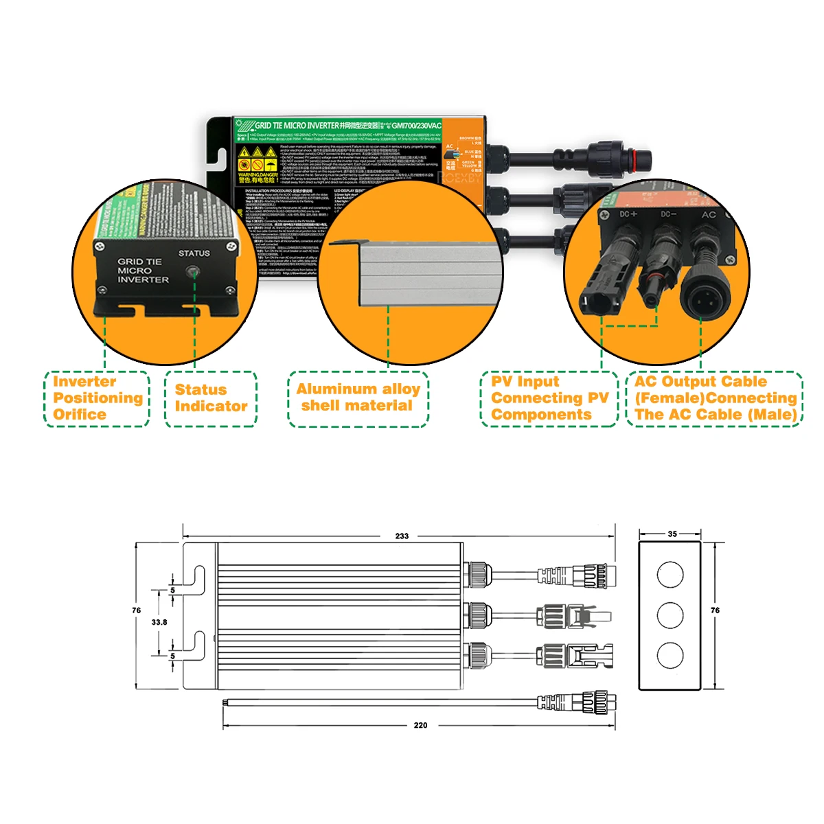
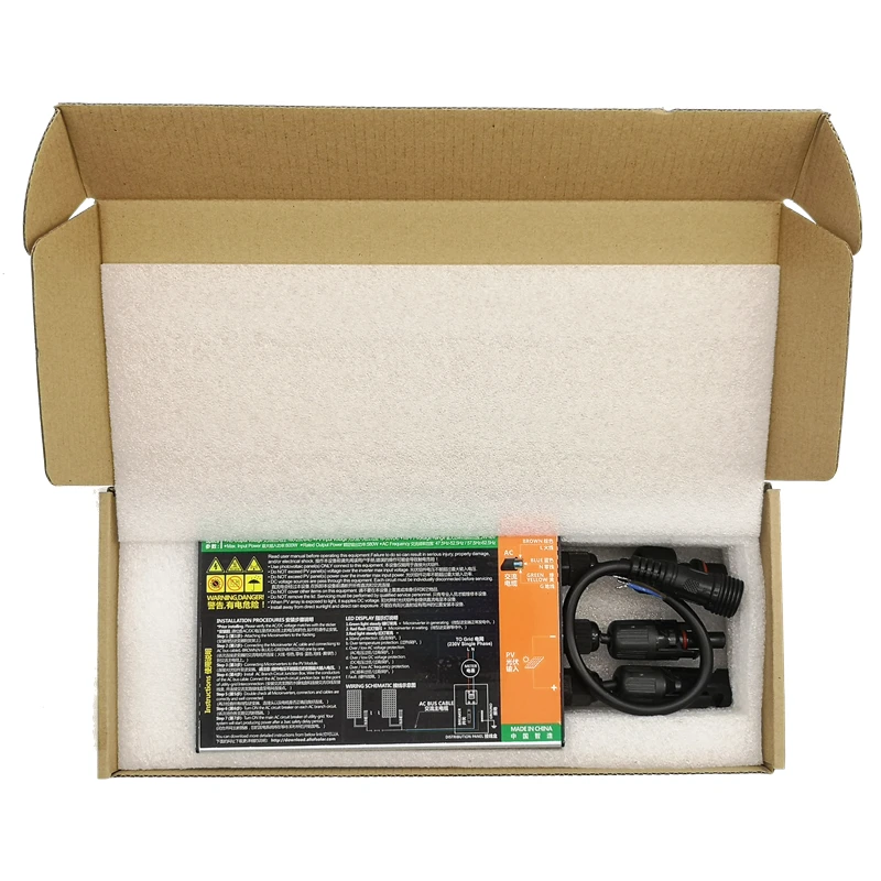
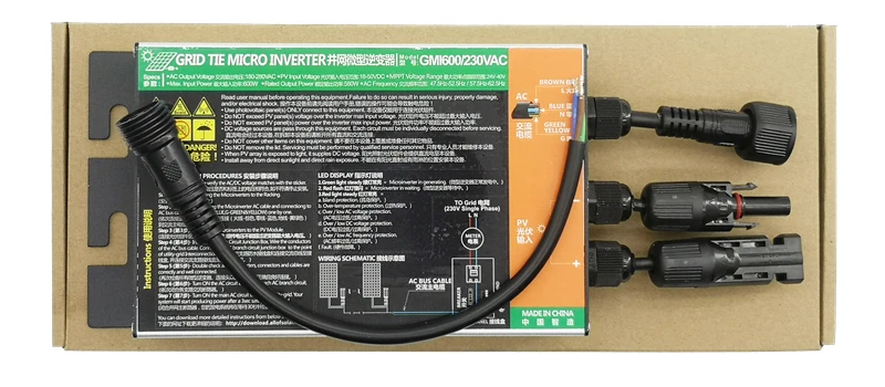
Package Include:
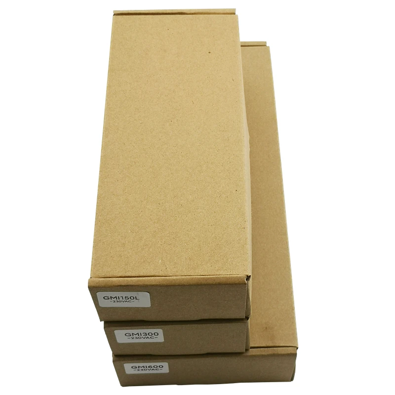
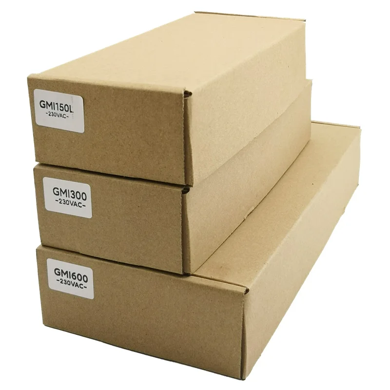
1XGrid Tie Inverter
1 x AC Cable 30CM
Dimensions
Product Series |
GMI260-350Series |
|||
Model |
GMI260 |
GMI300 |
GMI350 |
|
Input Data(DC,PV) | ||||
Number of Input MC4 Connector |
1 set |
|||
MPPT Voltage Range |
24V-40V |
|||
Operation Voltage Range |
18V-50V |
|||
Maximum Input Voltage |
50V |
|||
Startup Voltage |
18V |
|||
Maximum Input Power |
260W |
300W |
350W |
|
Maximum Input Current |
10.4A |
12A |
14A |
|
Output Data(AC) | ||||
Single-Phase Grid Type |
120V / 230V |
|||
Rated Output Power |
250W |
280W |
320W |
|
Maximum Output Power |
260W |
300W |
350W |
|
Nominal Output Current |
120V : 2.08A/230V : 1.08A |
120V : 2.33A/230V : 1.21A |
120V : 2.66A/230V : 1.39A |
|
Nominal Output Voltage |
120VAC / 230VAC |
|||
Default Output Voltage Range |
@120VAC : 80V-160V / @230VAC : 180V-280V |
|||
Nominal Output Frequency |
50Hz / 60Hz |
|||
Default Output Frequency Range |
@50Hz : 47.5Hz-52.5Hz / @60Hz : 57.5Hz-62.5Hz |
|||
Power Factor |
>0.99 |
|||
Total Harmonic Distortion |
THD <5% |
|||
Efficiency | ||||
Peak Efficiency |
92.5% |
|||
CEC Weighted Efficiency |
@120VAC : 90.5% / @230VAC : 91.5% |
|||
Nominal MPPT Efficiency |
99.9% |
|||
Night Power Consumption |
<700mW |
|||
Mechanical Data | ||||
Operating Ambient Temperature Range |
-40°C to +65°C |
|||
Storage Temperature Range |
-40°C to +85°C |
|||
Dimensions (W x H x D) |
35mm x 76mm x 233mm |
|||
Weight |
0.5kg |
|||
Waterproof Grade |
IP55 |
|||
Cooling Mode |
Natural Convection - No Fans |
|||
Other Features | ||||
Transformer Design |
High Frequency Transformers, Galvanic allyIsolated |
|||
Integrated Ground |
Equipment ground is provided by the PE in the AC cable. No additional ground is required. |
|||
Protection Functions |
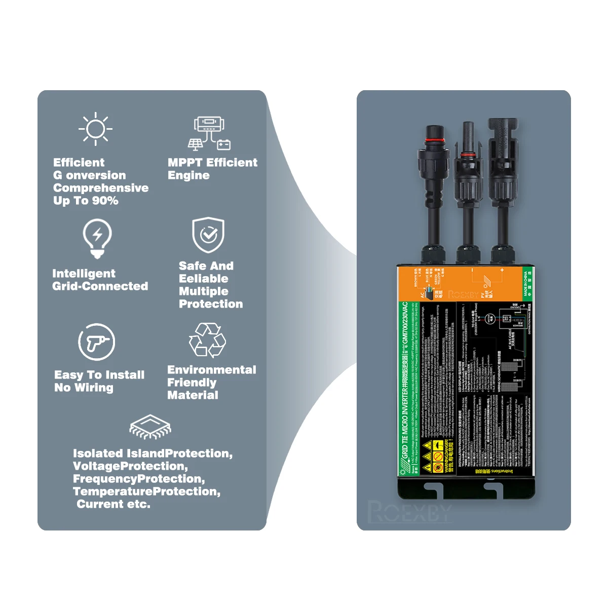
Isolated Island Protection, Voltage Protection, Frequency Protection, Temperature Protection, Current Protection, etc. |
|||
Product Series |
GMI500-700Series |
|||
Model |
GMI500 |
GMI600 |
GM700 |
|
Input Data(DC,PV) | ||||
Number of Input MC4 Connector |
1 set |
|||
MPPT Voltage Range |
24V-40V |
|||
Operation Voltage Range |
18V-50V |
|||
Maximum Input Voltage |
50V |
|||
Startup Voltage |
18V |
|||
Maximum Input Power |
500W |
600W |
700W |
|
Maximum Input Current |
20A |
24A |
28A |
|
Output Data(AC) | ||||
Single-Phase Grid Type |
120V / 230V |
|||
Rated Output Power |
490W |
580W |
650W |
|
Maximum Output Power |
500W |
600W |
700W |
|
Nominal Output Current |
120V : 4.08A/230V : 2.13A |
120V : 4.83A/230V : 2.52A |
120V : 5.41A/230V : 2.82A |
|
Nominal Output Voltage |
120VAC / 230VAC |
|||
Default Output Voltage Range |
@120VAC : 80V-160V / @230VAC : 180V-280V |
|||
Nominal Output Frequency |
50Hz / 60Hz |
|||
Default Output Frequency Range |
@50Hz : 47.5Hz-52.5Hz / @60Hz : 57.5Hz-62.5Hz |
|||
Power Factor |
>0.99 |
|||
Total Harmonic Distortion |
THD <5% |
|||
Efficiency | ||||
Peak Efficiency |
92% |
|||
CEC Weighted Efficiency |
@120VAC : 90% / @230VAC : 90.5% |
|||
Nominal MPPT Efficiency |
99.9% |
|||
Night Power Consumption |
<700mW |
|||
Mechanical Data | ||||
Operating Ambient Temperature Range |
-40°C to +65°C |
|||
Storage Temperature Range |
-40°C to +85°C |
|||
Dimensions (W x H x D) |
41mm x 106mm x 282mm |
|||
Weight |
0.95kg |
|||
Waterproof Grade |
IP55 |
|||
Cooling Mode |
Natural Convection - No Fans |
|||
Other Features | ||||
Transformer Design |
High Frequency Transformers, Galvanic allyIsolated |
|||
Integrated Ground |
Equipment ground is provided by the PE in the AC cable. No additional ground is required. |
|||
Protection Functions |
Isolated Island Protection, Voltage Protection, Frequency Protection, Temperature Protection, Current Protection, etc. |
|||
INSTALLATION PROCEDURES
*Prior to installing the Microinverters, Please verify that the utility voltage at the point of common grid connection matches the voltage rating on the Microinverter label.
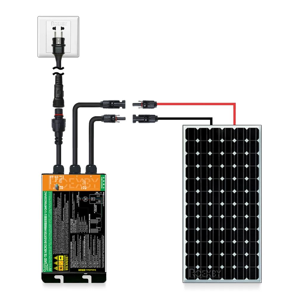
Step 1- Attaching the Microinverters to the Racking.
a. Mark the location of the Microinverter on the rack, with respect to the PV module junction box or any other obstructions.
b. Mount one Microinverter at each of these locations using hardware ecommended by your module racking vendor.
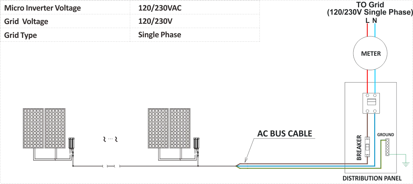
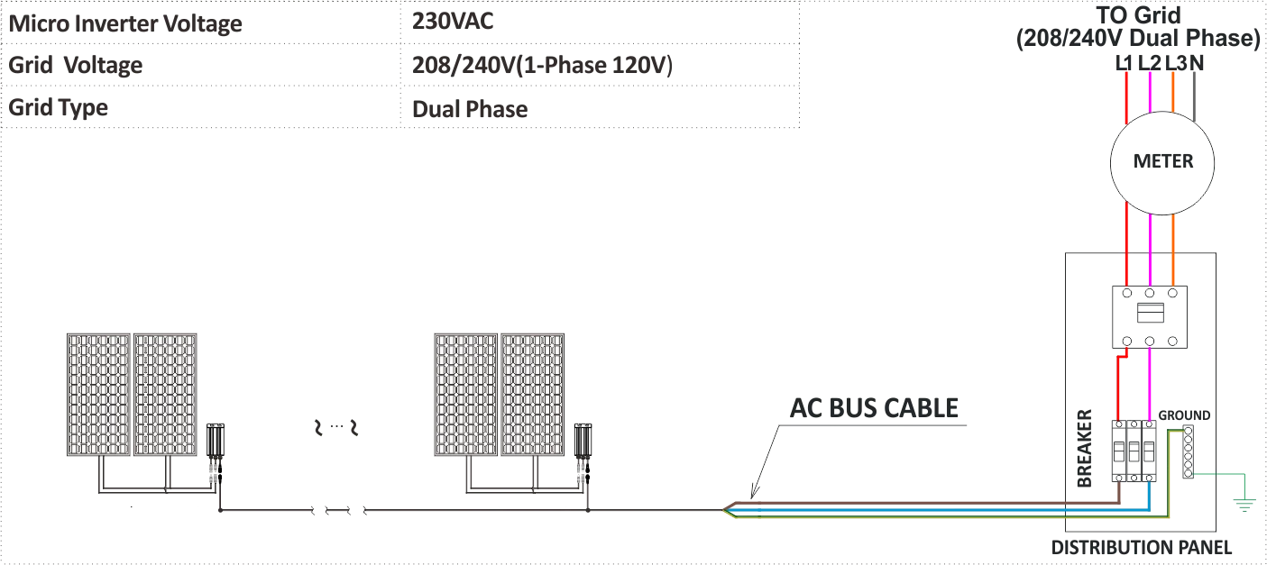
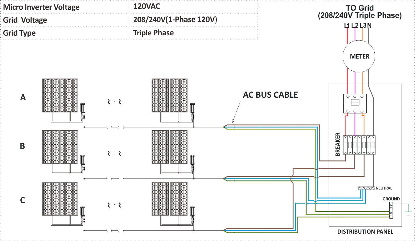
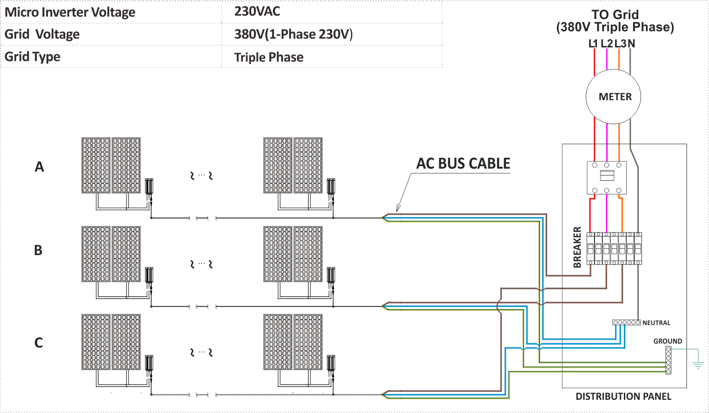
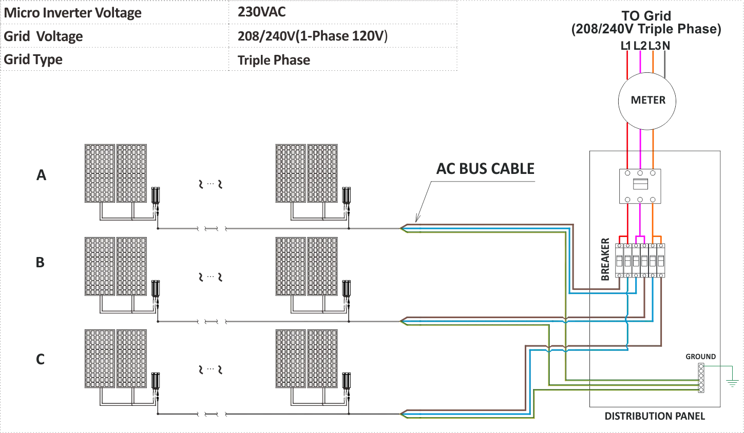
Step 2 - Connecting the Microinverter AC cable and connectiong to AC bus cable(L-BROWN,N-BLUE,GGREEN&YELLOW) one by one, Please do NOT exceed the Maximum current of AC bus cable .
Step 3 - Connecting Microinverters to the PV Module,Please do NOT exceed PV panel(s) VOC over inverter max input voltage.
Step 4 - Install the AC Branch Circuit Junction Box,Wire the conductors of the AC bus cable. Connect the AC branch circuit junction box to the point of utility-grid Interconnection.
Step 5 - Double check all Microinverters, connectors and cables are correctly and well connected.
Step 6 - Turn ON the AC circuit breaker on each AC branch circuit of Microinverter .
Step 7 - Turn ON the main AC circuit breaker of utility-grid. Your system will start producing powerafter a 3sec safety delay period.
